Fundamentals
Heat Exchanger Classification
Heat exchangers are devices that facilitate the transfer of thermal energy between two or more fluid streams at different temperatures. They are classified by several criteria (Shah & Sekulic, 2003):
| Criterion | Types |
|---|---|
| Flow arrangement | Counterflow, co-current (parallel flow), crossflow |
| Number of streams | 2-stream, multi-stream (3+) |
| Construction | Shell-and-tube, plate, plate-fin, spiral |
| Heat transfer mechanism | Sensible heat, latent heat (phase change), or both |
Multi-Stream Heat Exchangers
Multi-stream heat exchangers (MSHXs) allow three or more process streams to exchange heat simultaneously in a single piece of equipment. They are widely used in:
- Cryogenic processes — air separation units, LNG liquefaction (Hesselgreaves et al., 2017)
- Chemical plants — heat integration networks, pinch technology implementations
- Petroleum refining — crude distillation preheat trains
Why Multi-Stream?
A conventional heat exchanger network with \(N\) streams may require up to \(\frac{N(N-1)}{2}\) individual 2-stream exchangers. An MSHX consolidates these into a single unit, reducing capital cost, plot space, and piping complexity.
Key Performance Metrics
Heat Duty (\(Q\))
The rate of heat transfer between streams, determined by the enthalpy change:
For sensible heat only (no phase change), this simplifies to:
Sign Convention
In this implementation, \(Q > 0\) for hot streams (heat released) and \(Q < 0\) for cold streams (heat absorbed). Energy balance requires \(\sum Q_i + Q_{\text{leak}} = 0\).
Overall Heat Transfer Coefficient (\(U\))
The \(U\)-value represents the thermal resistance of the heat transfer path:
where \(h\) are convective coefficients, \(\delta_w/k_w\) is the wall conduction resistance, and \(R_f\) are fouling resistances (Incropera et al., 2007).
UA Product
The product \(UA\) (W/K) is the overall thermal conductance of the exchanger:
where \(\Delta T_{\text{eff}}\) is the effective mean temperature difference (LMTD for simple cases).
Minimum Internal Temperature Approach (MITA)
The MITA is the smallest temperature difference between the hot and cold composite curves at any point along the exchanger:
Temperature Crossover
If MITA < 0, the hot composite crosses below the cold composite — this is thermodynamically infeasible and indicates the specified conditions cannot be achieved.
Thermal Efficiency (\(\varepsilon\))
The effectiveness of the heat exchanger relative to the maximum possible heat transfer:
where \(C_{\min} = \min(\dot{m}_h c_{p,h},\; \dot{m}_c c_{p,c})\) is the minimum heat capacity rate (Kays & London, 1984).
Flow Arrangements
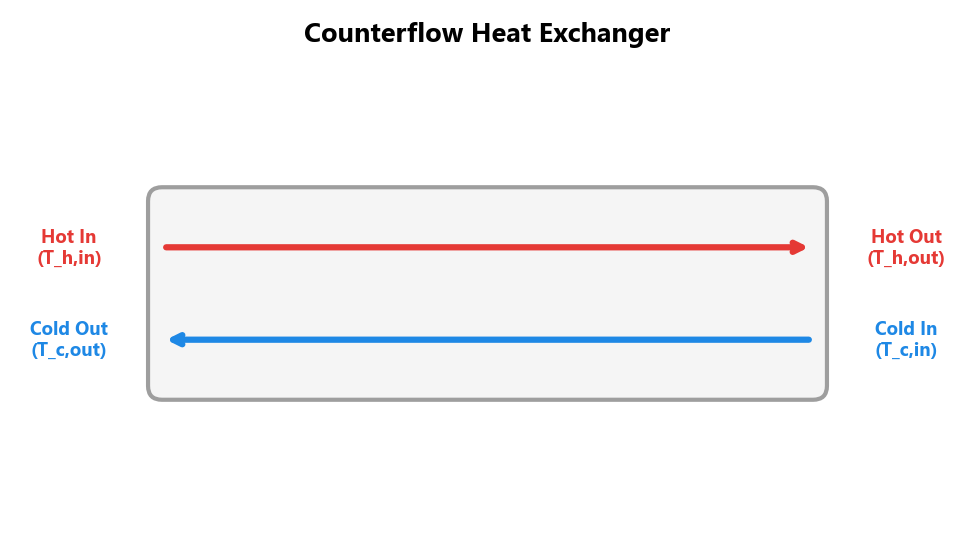
Counterflow
In counterflow, the hot and cold streams flow in opposite directions. This arrangement achieves the highest thermal efficiency and allows the cold outlet to approach the hot inlet temperature.
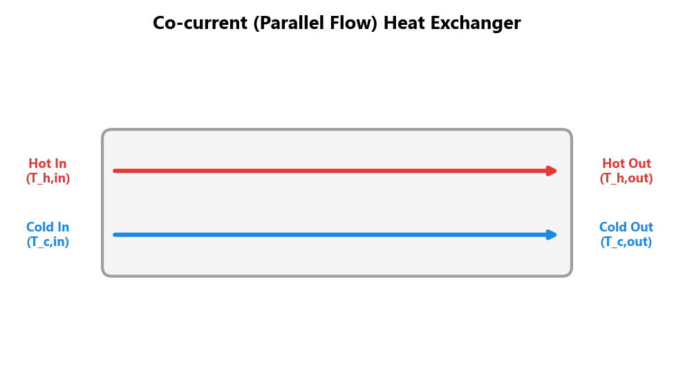
Co-current (Parallel Flow)
In co-current flow, both streams enter at the same end and flow in the same direction. The cold outlet temperature is always limited to be below the hot outlet temperature.
Counterflow vs Co-current
For the same UA and inlet conditions, counterflow always transfers more heat than co-current. Counterflow is the default and recommended configuration in most process applications.
Degrees of Freedom
For an MSHX with \(N\) streams:
| Given | Unknowns | Equations | DOF |
|---|---|---|---|
| All inlet T, all \(\dot{m}\) | \(N\) outlet temperatures | 1 energy balance + 1 constraint (UA or MITA) | \(N - 2\) |
- \(N = 2\): UA or MITA mode is fully determined (0 specs needed)
- \(N > 2\): User must specify \(N - 2\) outlet temperatures; the remaining two are found from energy balance + constraint
- Outlet Temperatures mode: User specifies all \(N\) outlets (or \(N-1\) with one auto-solved by energy balance)